A brief description of IEC motor starters:
When wiring a motor starter you must first understand a little about how it functions. We will try to touch on some of the basics here.
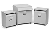
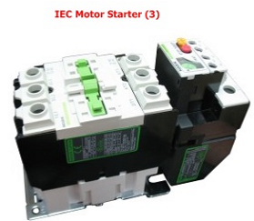
A motor starter (IEC Type pic 3) is primarily made up of at least two parts, a contactor and overload.
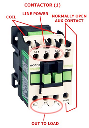
A contactor (pic 1) works like a relay. A coil is energized by voltage which creates a magnetic field; this magnetic field causes contact points close. The neat thing is that the voltage applied to the coil can be a different voltage than passes through the contact points. The other greater benefit is that it only takes a very small about of current to magnetize the contactor coil. This gives someone the ability to use switches and devices rated for very small power to control large power applications.
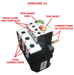
An overload (pic 2) is the second device needed to make up a motor starter. An IEC overload somewhat works like a relay also, and sometimes they are referred to as an overload relay. An overload is typically installed after a contactor and usually "attached" to the load side of the contactor. The IEC overloads Elimia typically uses are three pole (three phase) with normally open and normally closed contact sets. When a motor starter is activated, Voltage/Current passes through the contactor into the overload. Inside the overload are bi-metal strips or electronics that "change" as Current changes. The more Current the more change. The overloads used by Elimia can determine to some extent the Current through each pole separately. When the amount of Current exceeds a set point for a certain amount of time the overload will "trip". The set point is determined by a rotary dial made on the overload. On this dial are numbers representing Current. This is the relay function of the IEC overload. The contacts points on the overload are used to monitor this trip effect. Most commonly the normally closed contact is used to "break" power to the contactor coil and disengage the starter when the trip occurs.